

|
Product Details:
|
|
| Place of Origin: | China |
|---|---|
| Brand Name: | HILINK |
| Certification: | CE FCC Rohs |
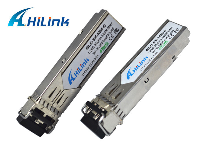
| Model Number: | GLC-SX-MM |
|
Payment & Shipping Terms:
|
|
| Minimum Order Quantity: | 1pcs |
| Price: | Negotiable |
| Packaging Details: | Blister Packaging ,10pcs/ tray |
| Delivery Time: | 1-3 days |
| Payment Terms: | T/T, Western Union |
| Supply Ability: | 10000pcs/ week |
|
Detail Information |
|||
| Wavelength: | 850nm | Data Rate: | 1.25Gbs |
|---|---|---|---|
| Distance: | 550m | Optical Power: | -8~-4dB |
| Sensitivity: | <-18 | Receiver: | PIN |
| DDM: | Yes | Connector: | SC, LC |
| High Light: | sfp fiber transceiver,sfp optical transceiver |
||
Product Description
The industry-standard Cisco Small Form-factor Pluggable (SFP) Gigabit Interface Converter is a hot-swappable input/output device that plugs into a Gigabit Ethernet port or slot, linking the port with the network. The 1000BASE-SX SFP is compatible with the IEEE 802.3z 1000BASE-SX standard and operates on 50 micrometer multimode fiber links up to 550 m and on 62.5 micrometer FDDI-grade multimode fibers up to 220 m.
| General | |
| Device Type | Transceiver module |
| Form Factor | Plug-in module |
| Width | 1.3 cm |
| Depth | 5.7 cm |
| Height | 0.9 cm |
| Networking | |
| Connectivity Technology | Wired |
| Cabling Type | Ethernet 100Base-BX |
| Data Link Protocol | Fast Ethernet |
| Compliant Standards | IEEE 802.3, IEEE 802.3ah |
| Min Operating Temperature | 0 °C |
| Max Operating Temperature | 70 °C |
| I. Pin Descriptions | ||||
| Pin | Symbol | Name/Description | Ref. | |
| 1 | VeeT | Transmitter Ground (Common with Receiver Ground) | 1 | |
| 2 | TX Fault | Transmitter Fault. | ||
| 3 | TX Disable | Transmitter Disable. Laser output disabled on high or open. | 2 | |
| 4 | MOD_DEF(2) | Module Definition 2. Data line for Serial ID. | 3 | |
| 5 | MOD_DEF(1) | Module Definition 1. Clock line for Serial ID. | 3 | |
| 6 | MOD_DEF(0) | Module Definition 0. Grounded within the module. | 3 | |
| 7 | Rate Select | No connection required | ||
| 8 | LOS | Loss of Signal indication. Logic 0 indicates normal operation. | 4 | |
| 9 | VeeR | Receiver Ground (Common with Transmitter Ground) | 1 | |
| 10 | VeeR | Receiver Ground (Common with Transmitter Ground) | 1 | |
| 11 | VeeR | Receiver Ground (Common with Transmitter Ground) | 1 | |
| 12 | RD- | Receiver Inverted DATA out. AC Coupled | ||
| 13 | RD+ | Receiver Non-inverted DATA out. AC Coupled | ||
| 14 | VeeR | Receiver Ground (Common with Transmitter Ground) | 1 | |
| 15 | VccR | Receiver Power Supply | ||
| 16 | VccT | Transmitter Power Supply | ||
| 17 | VeeT | Transmitter Ground (Common with Receiver Ground) | 1 | |
| 18 | TD+ | Transmitter Non-Inverted DATA in. AC Coupled. | ||
| 19 | TD- | Transmitter Inverted DATA in. AC Coupled. | ||
| 20 | VeeT | Transmitter Ground (Common with Receiver Ground) | 1 | |
Notes:
MOD_DEF(0) pulls line low to indicate module is plugged in.
LOS is LVTTL output. Should be pulled up with 4.7k – 10kohms on host board to a voltage between 2.0V and 3.6V. Logic 0 indicates normal operation; logic 1 indicates loss of signal.
Mechanical Spec
![]()
Enter Your Message
| Shenzhen HiLink Technology Co.,Ltd. |
| 11F DongMing Building, Minzhi Street, Longhua District, Shenzhen , China |
| 86-755-2335-7706 |
| steve@hilinktech.com |

